Based on training materials by EnerSys
Introduction: The Enduring Power of Lead-Acid
Despite the surge in new battery technologies, the lead-acid battery remains the backbone of backup power for telecommunications, utilities, and UPS systems globally. Its technology traces back to 1859, when Gaston Planté immersed lead sheets in sulfuric acid to create the first rechargeable battery. Even more surprisingly, the concept dates back 2000 years to the "Baghdad Battery"—an earthenware pot containing a copper cylinder and iron rod that could generate nearly 2 volts.
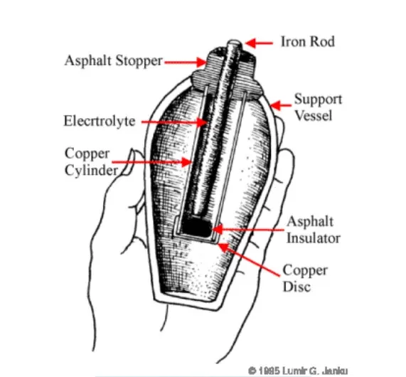 Figure 1: Baghdad Battery
Today, the fundamental chemistry remains largely unchanged, but the engineering has evolved significantly. For technicians and facility managers, understanding these fundamentals is not just academic—It is the foundation of predictive maintenance and the key to preventing catastrophic failure.
1. Battery Construction and Chemistry
At its core, a lead-acid battery cell produces approximately 2 volts. It consists of two dissimilar electrodes immersed in an electrolyte (sulfuric acid).
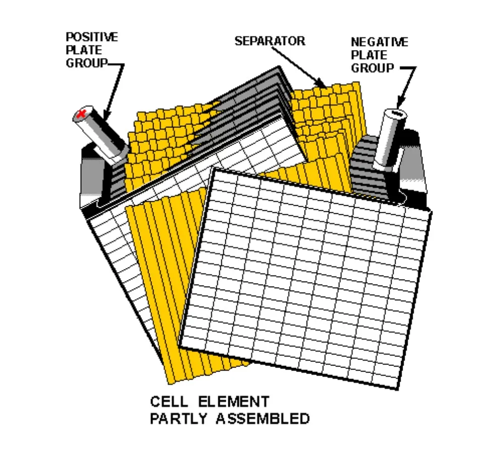 Figure 2: Battery Construction and Chemistry
- Positive Plate: Lead Dioxide (PbO2) – Dark chocolate brown or black when healthy.
- Negative Plate: Sponge Lead (Pb) – Gray in color.
- Electrolyte: Dilute Sulfuric Acid (H2SO4).
The Discharge Cycle During a power outage, the battery discharges. Both the positive and negative plates convert to Lead Sulfate (PbSO4), and the acid turns into water. As the sulfate layer grows on the plates, the battery's voltage drops.
The Recharge Cycle Charging reverses this process. The lead sulfate is converted back into lead dioxide and sponge lead, and the water returns to sulfuric acid.
- If a battery sits discharged for too long, the lead sulfate crystals harden. This "sulfation" is permanent and is a primary cause of capacity loss.
- Note for monitoring: This is why tracking discharge depth and duration is critical; once sulfation sets in, the battery’s internal resistance rises, which can be detected by modern monitoring systems.
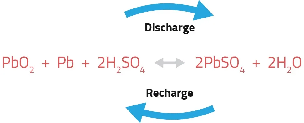 Figure 3: Discharge/Recharge Cycle
The Grid Alloy Factor
The "grid" supports the active material and carries the current. The alloy used in this grid dictates the battery's behavior:
- Lead-Calcium: The standard for standby power. It offers low water consumption, low self-discharge, and stable float currents.
- Lead-Antimony/Selenium: Older technology. Excellent for cycling but suffers from "poisoning" over time, leading to high water consumption and frequent maintenance requirements.
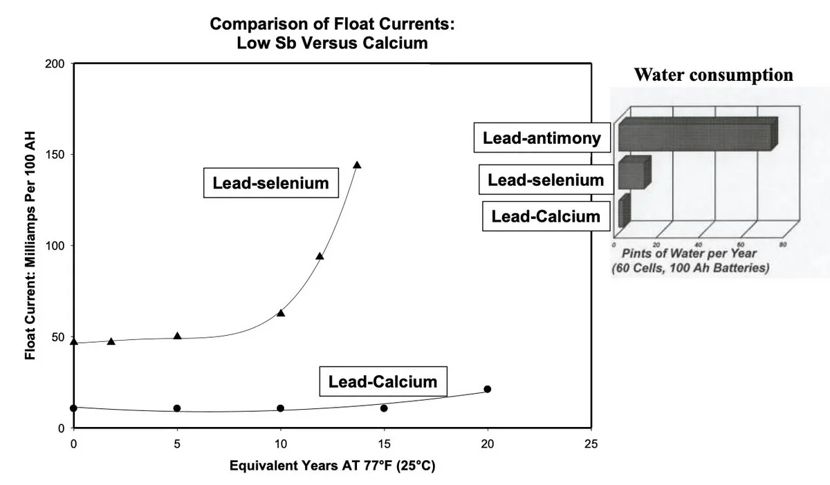 Figure 4: Comparison of Float Currents
2. VLA vs. VRLA: Understanding the Difference
The industry divides batteries into two main categories: Vented Lead-Acid (VLA) and Valve-Regulated Lead-Acid (VRLA).
VLA (Flooded/Wet Cells) These are the traditional batteries in clear jars. They vent oxygen and hydrogen freely.
- Pros: Longest life (20+ years), easier to troubleshoot (you can see the plates), extremely reliable.
- Cons: Requires regular watering, specific ventilation, spill containment, and a larger footprint.
VRLA (Sealed/Maintenance-Free) These batteries are sealed, except for a pressure relief valve. They use a recombination process where generated oxygen and hydrogen recombine into water inside the cell (~99% efficiency).
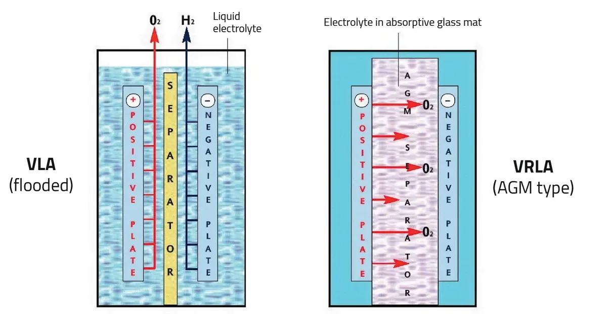 Figure 5: VLA/VRLA Comparison
- Types:
- AGM (Absorbed Glass Mat): Acid is held in a sponge-like fiberglass mat. High power density, widely used in UPS
- Gel: Acid is mixed with silica to form a solid gel. Better thermal properties, often used in harsh environments.
- Pros: Compact, no watering, minimal ventilation needed.
- Cons: Shorter life, sensitive to heat, and "dryout" (permanent water loss) is the #1 failure mode.
Note: Because you cannot open the jar to add water, monitoring internal impedance/conductance is the only reliable way to detect dryout before the load drops.
3. Application-Specific Design
Not all batteries are created equal. A battery designed for a telecom hut will fail prematurely in a data center UPS.
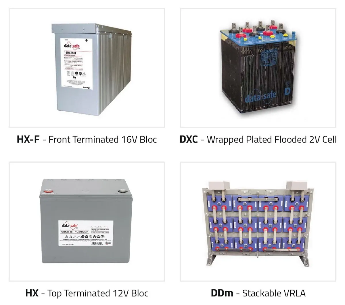 Figure 6: Batteries
| Application | Discharge Profile | Battery Characteristics |
|---|---|---|
| Telecom | Long duration (4–8 hours) with few cycles. | Thicker positive plates and high electrolyte volume, specifically designed for long, slow drains. |
| UPS | High intensity, short duration (typically 15 minutes). | Thin plates packed tightly together to maximize surface area for rapid power release. |
| Utility/Switchgear | Spikey duty cycle (long drain + momentary high current pulses). | Balanced design. Must handle 1-minute bursts for breaker tripping and multi-hour loads. |
4. The Art of Charging
Proper charging is the single most important factor in battery life.
Float Charging This is the normal operating mode. The charger provides just enough current to overcome the battery's natural self-discharge.
- Danger Zone:
- Undercharging: Causes sulfation.
- Overcharging: Causes "positive grid corrosion" (the plate literally rusts away) and water loss (gassing).
Temperature Compensation Batteries are chemical devices, and heat accelerates chemical reactions.
- Rule of Thumb: For every 15°F to 18°F (8-10°C) rise above 77°F (25°C), battery life is cut in half.
- Chargers must be temperature compensated. As temperature rises, charge voltage should decrease (approx. 2.8mV per degree F) to prevent thermal runaway.
- Monitoring Tip: Ambient room temperature is often insufficient. Sensors should be placed at the negative post of cells to capture the true internal temperature of the string.
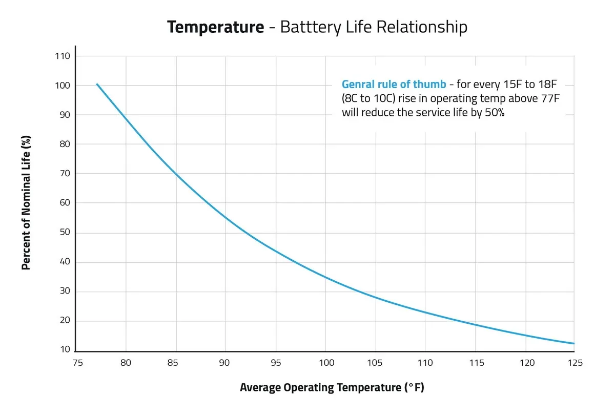 Figure 7: Temperature - Battery life relationship
AC Ripple Dirty power from the charger (AC ripple) creates internal heating and accelerates aging. It acts as micro-cycles that wear out the active material.
5. Installation and Maintenance Best Practices
Handling and Safety
- Never lift a battery by its terminal posts. This breaks the internal seal and voids the warranty.
- Use insulated tools to prevent short circuits
- Chemical Warning: Never use petroleum-based lubricants or cleaners on battery jars. They react with the plastic and cause stress cracks. Use only approved silicon grease (e.g., NO-OX-ID).
Torque is Critical Loose connections cause high resistance and heat, potentially melting the post (a catastrophic failure). Always use a calibrated torque wrench and follow manufacturer specifications.
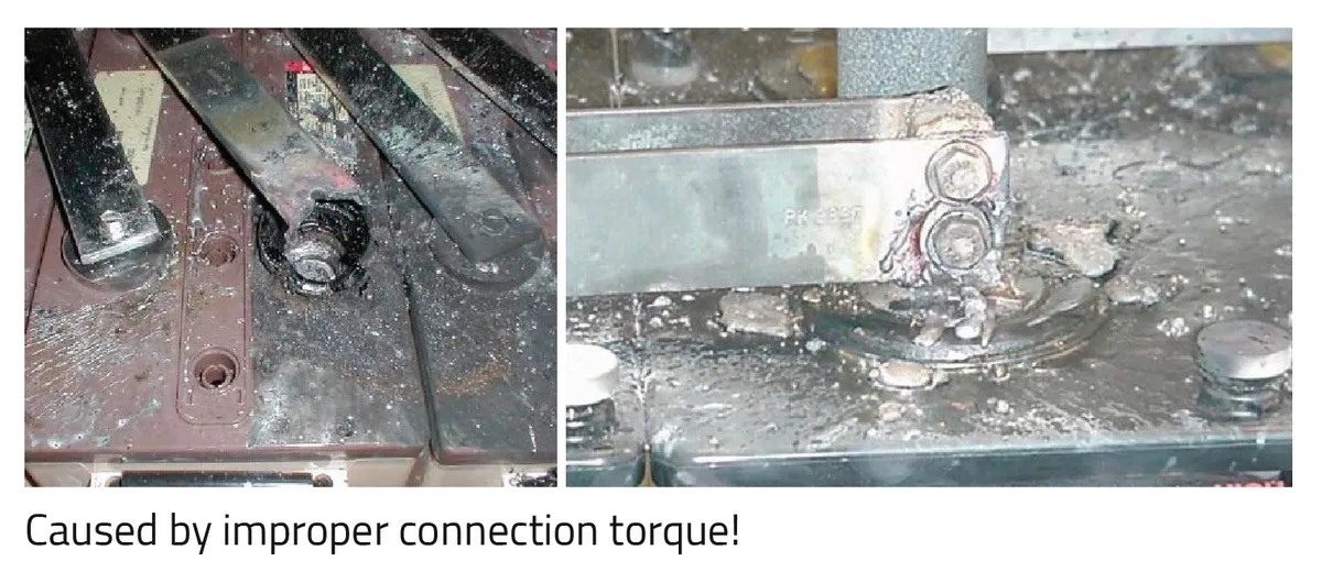 Figure 8: Improper connection torque
Visual Inspection: The Technician's Best Tool High-tech meters are useful, but eyes and a flashlight are irreplaceable. Look for:
- Sediment: Is debris piling up at the bottom of a VLA jar?
- Color: Healthy positive plates are dark chocolate brown. Pale or white plates indicate sulfation.
- Shape: Bulging VRLA jars indicate overcharging or thermal issues.
- Corrosion: White powder at the terminals indicates a seal leak.
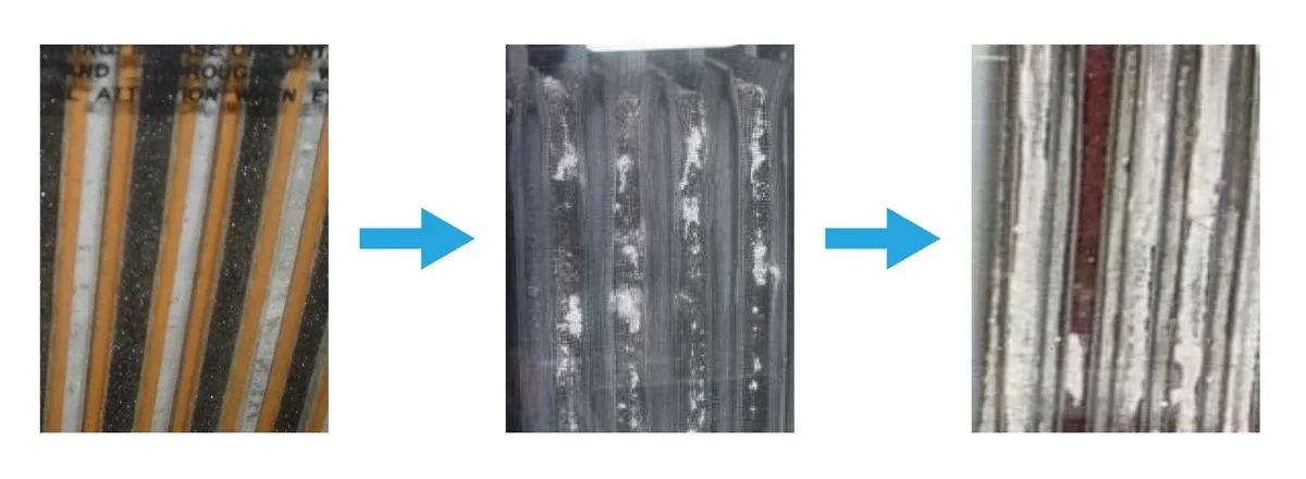 Figure 9: Visual Inspection
Capacity Testing While discharge testing is the only way to get the real battery capacity, it is often economically impractical. Monitoring State of Health (SOH) via internal resistance provides a daily health trend, alerting you to degradation months before the annual discharge test.
- IEEE Standards: IEEE-450 (VLA) and IEEE-1188 (VRLA) recommend performance tests within the first 2 years, then at 25% intervals of expected life, and annually once the battery degrades to 85% capacity.
- End of Life: A battery is considered failed when it reaches 80% of its rated capacity.
Conclusion
Lead-acid batteries are resilient, but they are not immortal. They are "sacrificial" devices that degrade with every day of use. By understanding the specific needs of your application—whether it's the high-current demand of a UPS or the long-term stability of a Telecom site—and adhering to strict maintenance schedules or continuous monitoring paired with annual visual inspections, you can ensure that when the lights go out, your power stays on.